11 RRLL: Math
Racket Rogue-Like Library: Math Functions
Common mathematical routines used for many RRLL modules.
11.1 Basic Math Utilities
| (require rrll/math/util) | package: rrll-math |
Additional math functions for fixnums and flonums.
11.2 Coordinate Systems
The main coordinate systems used in the project are:
Screen coordinates (x y)
Map coordinates (x y z 1)
Camera coordinates (x y z w) and (x y w)
These coordinates and their transformations are used in the rendering pipeline.
A set of functions for working with vectors in affine and projective spaces is implemented throghout the following modules.
11.2.1 Screen Coordinates
The screen – represented by canvas – is a two-dimensional plane with origin in the upper-left corner and the X coordinate growing from left to right and the Y coordinate growing from top to bottom.
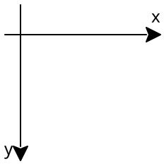
The screen coordinates are represented as fixnum? values.
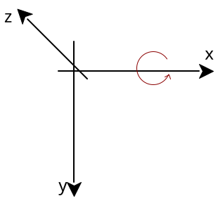
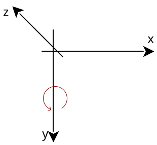
11.2.2 Map Coordinates
The world map is represented from the top view with origin – as the screen – with the origin at the top-left corner and the X coordinate growing from left to riht and the Y coordinate growing from top to bottom.
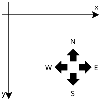
The respective compass directions North, East, South and West are shown in the picture as well.
For all practical purposes their respective azimut angles are clockwise from 0 pointing north:
north \varphi=0
east \varphi=\frac{\pi}{2}
south \varphi=\pi
west \varphi=\frac{3\pi}{2}
The Z coordinate representing the height on the map grows from below the map up.
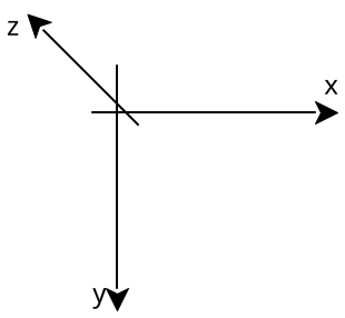
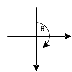
The inclination starts at \theta=0 for looking north (towards negative Y). Positive inclination goes up to \theta=\frac{\pi}{2} looking straight up in positive Z direction or down to \theta=-\frac{\pi}{2} looking straight down in negative Z direction.
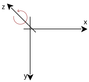
11.2.3 Transformations in Map Coordinates
The simplest transformation is translation by given vector \vec{t} can be represented by the following matrix:
\vec{t}=(x_y,y_t,z_t)
T=\begin{bmatrix} 1 & 0 & 0 & x_t \\ 0 & 1 & 0 & y_t \\ 0 & 0 & 1 & z_t \\ 0 & 0 & 0 & 1 \\ \end{bmatrix}
Rotation around the Z axis counter-clockwise by the angle \theta is:
Z=\begin{bmatrix} \cos\theta & \sin\theta & 0 & 0 \\ -\sin\theta & \cos\theta & 0 & 0 \\ 0 & 0 & 1 & 0 \\ 0 & 0 & 0 & 1 \\ \end{bmatrix}
Rotation around the X axis counter-clockwise by the angle \theta is:
X=\begin{bmatrix} 1 & 0 & 0 & 0 \\ 0 & \cos\theta & \sin\theta & 0 \\ 0 & -\sin\theta & \cos\theta & 0 \\ 0 & 0 & 0 & 1 \\ \end{bmatrix}
Rotation around the Y axis counter-clockwise by the angle \theta is:
Y=\begin{bmatrix} \cos\theta & 0 & -\sin\theta & 0 \\ 0 & 1 & 0 & 0 \\ \sin\theta & 0 & \cos\theta & 0 \\ 0 & 0 & 0 & 1 \\ \end{bmatrix}
11.2.4 Camera Coordinates
The 3D coordinates used for populating the world with polygons from the map and the camera coordinates share a similar same coordinate system.
The X coordinate grows from left to right, the Y coordinate grows from top to bottom and the Z coordinate grows into the screen.
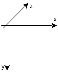
After applying camera translation and all rotations, the axis are flipped to represent the point in camera coordinate axes using the following matrix:
M=\begin{bmatrix} 1 & 0 & 0 & 0 \\ 0 & 0 & -1 & 0 \\ 0 & -1 & 0 & 0 \\ 0 & 0 & 0 & 1 \\ \end{bmatrix}
It switches the axes as follows:
x_w=x_m y_w=-z_m z_w=-y_m w_w=w_m
With camera axes in place the projective transformation to camera projective coordinates is performed using the projection matrix. The following parameters are used:
r - pixel aspect ratio: pixel width over pixel height
w - camera canvas width in pixels
h - camera canvas height in pixels
n - near plane Z distance
f - far plane Z distance
Because of limitations of the 24-bit fixed-point w-buffer (TODO), the near-plane distance has to be fixed:
n=0.1
The far-plane distance can be almost anything but for all practical purposes the following is used:
n=100
The projection assumes 90^\circ viewing angle in the smaller canvas dimension and slightly bigger viewing angle in the other dimension that gets calculated from the camera canvas width and height.
First, primary lens size is calculated:
w<=h\Rightarrow l=w w>h\Rightarrow l=h
Then width and height aspect ratio is computed:
r_w=\frac{w}{l} r_h=\frac{h}{l}
The projection matrix is then as follows:
P=\begin{bmatrix} \frac{2\cdot n\cdot r}{r_w} & 0 & 0 & 0 \\ 0 & \frac{2\cdot n}{r_h} & 0 & 0 \\ 0 & 0 & \frac{f+n}{f-n} & 1 \\ 0 & 0 & \frac{2\cdot f\cdot n}{f-n} & 0 \\ \end{bmatrix}
After applying the projection matrix the vertices are in camera projective coordinates. Clipping against frustum is performed in these coordinates.
11.2.5 Vector Projection
Any point in camera projective coordinates can be represented as:
P=(x_p,y_p,z_p,w_p)
A screen vector then is:
S=(x_s,y_s,w_s)
The projection is as follows:
x_s=w\cdot\frac{x_p+1}{2\cdot w_p} y_s=w\cdot\frac{y_p+1}{2\cdot w_p} w_s=w_p
The screen coordinates must be rounded to the nearest integer.
11.3 Generic Linear Algebra
11.3.1 Generic 2D Vectors
| (require rrll/math/algebra2) | package: rrll-math |
These procedures help with basic map vector handling.
procedure
(flvec2-linear A B v) → flvector?
A : flvector? B : flvector? v : flonum?
C=A+v\cdot(B-A)
procedure
(flvec2-values A) →
flonum? flonum? A : flvector?
11.3.2 Generic 3D Vectors
| (require rrll/math/algebra3) | package: rrll-math |
procedure
(flbec3-dot v1 v2) → flonum?
v1 : flvector? v2 : flvector?
d=\vec{v_1}\cdot\vec{v_2} d=x_{v_1}\cdot x_{v_2}+y_{v_1}\cdot y_{v_2}+z_{v_1}\cdot z_{v_2}
procedure
(flvec3-length v) → flonum?
v : flvector?
l=\sqrt{\vec{v}\cdot \vec{v}} l=\sqrt{x_v^2+y_v^2+z_v^2}
procedure
(flvec3-length^2 v) → flonum?
v : flvector?
l^2=x_v^2+y_v^2+z_v^2
procedure
(flvec3-dist A B) → flonum?
A : flvector? B : flvector?
d=\sqrt{(x_A-x_B)^2+(y_A-y_B)^2+(z_A-z_B)^2}
procedure
(flvec3-dist^2 A B) → flonum?
A : flvector? B : flvector?
d^2=(x_A-x_B)^2+(y_A-y_B)^2+(z_A-z_B)^2
procedure
(flvec3-mul v n) → flvector?
v : flvector? n : flonum?
\vec{v{}’}=n\cdot \vec{v} \vec{v}=(x_v,y_v,z_v) \vec{v{}’}=(x_v{}’,y_v{}’,z_v{}’) \vec{v{}’}=(n\cdot x_v,n\cdot y_v,n\cdot z_v)
procedure
(flvec3-div v n) → flvector?
v : flvector? n : flonum?
\vec{v{}’}=\frac{v}{n} \vec{v{}’}=\frac{1}{n}\cdot \vec{v}
procedure
(flvec3-normalize v) → flvector?
v : flvector?
procedure
(flvec3-values v) →
flonum? flonum? flonum? v : flvector?
procedure
(flvec3-linear A B v) → flvector?
A : flvector? B : flvector? v : flonum?
C=A+v\cdot(B-A)
procedure
(flvec3-add A B) → flvector?
A : flvector? B : flvector?
procedure
(flvec3-neg A) → flvector?
A : flvector?
procedure
(flvec3-sub A B) → flvector?
A : flvector? B : flvector?
procedure
(flvec3-cross A B) → flvector?
A : flvector? B : flvector?
C=A\times B A=(x_A,y_A,z_A) B=(x_B,y_B,z_B) C=(x_C,y_C,z_C) x_C=y_A\cdot z_B-z_A\cdot y_B y_C=z_A\cdot x_B-x_A\cdot z_B z_C=x_A\cdot y_B-y_A\cdot x_B
11.4 Normalized Projective 3D Linear Algebra
| (require rrll/math/algebra4) | package: rrll-math |
This module handles the basic vector transformation in 4D affine vector space representing 3D projective vector space.
11.4.1 Normalized Projective 3D Vectors
The first part of this module implements the basic affine 4D vector operations.
procedure
(flvec4 [a b c d]) → flvector?
a : flonum? = 0.0 b : flonum? = 0.0 c : flonum? = 0.0 d : flonum? = 1.0
procedure
(flvec4-values v) →
flonum? flonum? flonum? flonum? v : flvector?
procedure
v1 : flvector? v2 : flvector? precision : flonum? = 0.0001
procedure
(flvec4-add v1 v2) → flvector?
v1 : flvector? v2 : flvector?
procedure
(flvec4-neg v) → flvector?
v : flvector?
procedure
(flvec4-sub v1 v2) → flvector?
v1 : flvector? v2 : flvector?
procedure
(flvec4-mul v n) → flvector?
v : flvector? n : flonum?
procedure
(flvec4-linear A B v) → flvector?
A : flvector? B : flvector? v : flonum?
procedure
(flvec4-project v) → flvector?
v : flvector?
\vec{v}=(x_v,y_v,z_v,w_v) \vec{v}{}’=(x_v{}’,y_v{}’,z_v{}’,w_v{}’) x_v{}’=\frac{x_v}{w_v} y_v{}’=\frac{y_v}{w_v} z_v{}’=\frac{z_v}{w_v} w_v{}’=w_v
procedure
(flvec4-unproject v) → flvector?
v : flvector?
\vec{v}=(x_v,y_v,z_v,w_v) \vec{v}{}’=(x_v{}’,y_v{}’,z_v{}’,w_v{}’) x_v{}’=x_v\cdot w_v y_v{}’=y_v\cdot w_v z_v{}’=z_v\cdot w_v w_v{}’=w_v
11.4.2 Normalized 3D Transformation Matrices
These functions implement construction and application of 4\times 4 matrices.
procedure
(flmat4 [ r0c0 r0c1 r0c2 r0c3 r1c0 r1c1 r1c2 r1c3 r2c0 r2c1 r2c2 r2c3 r3c0 r3c1 r3c2 r3c3]) → flvector? r0c0 : flonum? = 0.0 r0c1 : flonum? = 0.0 r0c2 : flonum? = 0.0 r0c3 : flonum? = 0.0 r1c0 : flonum? = 0.0 r1c1 : flonum? = 0.0 r1c2 : flonum? = 0.0 r1c3 : flonum? = 0.0 r2c0 : flonum? = 0.0 r2c1 : flonum? = 0.0 r2c2 : flonum? = 0.0 r2c3 : flonum? = 0.0 r3c0 : flonum? = 0.0 r3c1 : flonum? = 0.0 r3c2 : flonum? = 0.0 r3c3 : flonum? = 0.0
M=\begin{bmatrix} r0c0 & r0c1 & r0c2 & r0c3 \\ r1c0 & r1c1 & r1c2 & r1c3 \\ r2c0 & r2c1 & r2c2 & r2c3 \\ r3c0 & r3c1 & r3c2 & r3c3 \\ \end{bmatrix}
procedure
(flmat4-unit) → flvector?
M=\begin{bmatrix} 1 & 0 & 0 & 0 \\ 0 & 1 & 0 & 0 \\ 0 & 0 & 1 & 0 \\ 0 & 0 & 0 & 1 \\ \end{bmatrix}
procedure
(flmat4*flvec4 M v) → flvector?
M : flvector? v : flvector?
M=\begin{bmatrix} M_{0,0} & M_{0,1} & M_{0,2} & M_{0,3} \\ M_{1,0} & M_{1,1} & M_{1,2} & M_{1,3} \\ M_{2,0} & M_{2,1} & M_{2,2} & M_{2,3} \\ M_{3,0} & M_{3,1} & M_{3,2} & M_{3,3} \\ \end{bmatrix}
\vec{v}=(x_v,y_v,z_v,w_v) \vec{v}{}’=(x_v{}’,y_v{}’,z_v{}’,w_v{}’) x_v{}’=M_{0,0}\cdot x_v+M_{0,1}\cdot y_v+M_{0,2}\cdot z_v+M_{0,3}\cdot w_v y_v{}’=M_{1,0}\cdot x_v+M_{1,1}\cdot y_v+M_{1,2}\cdot z_v+M_{1,3}\cdot w_v z_v{}’=M_{2,0}\cdot x_v+M_{2,1}\cdot y_v+M_{2,2}\cdot z_v+M_{2,3}\cdot w_v w_v{}’=M_{3,0}\cdot x_v+M_{3,1}\cdot y_v+M_{3,2}\cdot z_v+M_{3,3}\cdot w_v
\begin{bmatrix}x_v{}’\\y_v{}’\\z_v{}’\\w_v{}’\end{bmatrix}= \begin{bmatrix} M_{0,0} & M_{0,1} & M_{0,2} & M_{0,3} \\ M_{1,0} & M_{1,1} & M_{1,2} & M_{1,3} \\ M_{2,0} & M_{2,1} & M_{2,2} & M_{2,3} \\ M_{3,0} & M_{3,1} & M_{3,2} & M_{3,3} \\ \end{bmatrix}\cdot \begin{bmatrix}x_v\\y_v\\z_v\\w_v\end{bmatrix}
procedure
(flmat4-ref m r c) → flonum?
m : flvector? r : fixnum? c : fixnum?
procedure
(flmat4*flmat4 m1 m2) → flvector?
m1 : flvector? m2 : flvector?
procedure
(flmat4* mat ...) → flvector?
mat : flvector?
11.5 Transformations in World/Camera Coordinates
| (require rrll/math/transform4) | package: rrll-math |
This module contains useful matrices for working in world/camera coordinates.
procedure
(flmat4-rotZ theta) → flvector?
theta : flonum?
procedure
(flmat4-rotX theta) → flvector?
theta : flonum?
procedure
(flmat4-rotY theta) → flvector?
theta : flonum?
procedure
(flmat4-translate x y z) → flvector?
x : flonum? y : flonum? z : flonum?
procedure
(flmat4-scale [x y z]) → flvector?
x : flonum? = 1.0 y : flonum? = 1.0 z : flonum? = 1.0
procedure
(flmat4-map->camera) → flvector?
procedure
(flmat4-project-unit near far width height [ pixel-aspect]) → flvector? near : flonum? far : flonum? width : (or/c fixnum? flonum?) height : (or/c fixnum? flonum?) pixel-aspect : (or/c #f flonum?) = #f
procedure
(flmat4-project near far width height [ pixel-aspect]) → flvector? near : flonum? far : flonum? width : (or/c fixnum? flonum?) height : (or/c fixnum? flonum?) pixel-aspect : (or/c #f flonum?) = #f
11.6 Angle Manipulation Helpers
| (require rrll/math/angles) | package: rrll-math |
This module contains simple functions for working with angles in the range \langle 0;2\pi\rangle.
Angles in this module and other related modules represented in 2D map coordinates point in the north direction for zero angle rotating clockwise as the angle increases.
procedure
(angle-subtract a1 a2) → flonum?
a1 : flonum? a2 : flonum?
procedure
(angle-wrap theta) → flonum?
theta : flonum?
procedure
(angle-flvec3 theta) → flvector?
theta : flonum?
procedure
(azimuth-name theta) → string?
theta : flonum?
11.7 2D Integer Vectors
| (require rlgrid/vec2) |
A convenience structure for representing 2D coordinates in the grid. The x and y values can only be fixnum?s.